EMFISIS Instrument Description
The EMFISIS instrumentation suite provides measurements of wave electric and magnetic fields as well as DC magnetic fields for the Van Allen Probes mission . EMFISIS provides a comprehensive set of wave electric and magnetic field measurements covering the frequency range from 10 Hz up to 400 kHz. EMFISIS comprises two sensors: a tri-axial fluxgate magnetometer (MAG) and a trixaxial AC magnetic search coil magnetometer (MSC). Additionally, to measure AC signals the Waves experiment which includes AC electric fields (from the EFW) experiment and a tri-axial search coil magnetometer. These instruments are welded into one integrated whole by a Main Electronics Box (MEB) which ties all measurements together for maximum impact on the Van Allen Probes.
The majority of the electronics are contained within the Main Electronics box comprised of seven printed circuit boards. From bottom to top, is first the Low Voltage Power Supply (LVPS) which converts primary spacecraft power to voltages used by the rest of the suite, followed by the Central Data Processing Unit which controls the suite and handles data transfer to and from the central spacecraft systems. Above this are the four boards of the Waves component of the EMFISIS system: two FFT engine boards and the AC electric field and AC magnetic field receivers. Completing the stack is the MAG drive, sampling, and heater control board.
Magnetometer
The EMFISIS magnetometer is the latest in a series of magnetic field investigations developed by the research group at GSFC. This magnetometry group has a long and successful track record of development and implementation of complex magnetic field investigations for planetary exploration, earth observing, and space physics missions. The sensors and analog electronics are "off-the-shelf" designs which have been or are being flown on numerous NASA missions including Juno, Messenger, and STEREO.
The STEREO instruments were themselves based on more than fifty magnetometers previously developed for space missions, from Voyager (still operational after more than 28 years in space), ISPM, GIOTTO, WIND, ACE, CLUSTER I & II (more than 10 instruments), DMSP (11 instruments) to the more recent Lunar Prospector, and Mars Global Surveyor instruments. They represent state‑of‑the‑art instruments with unparalleled performance.
The EMFISIS fluxgate magnetometer is a wide-range, high performance triaxial fluxgate magnetometer system. The signal processing, analog to digital converter (A/D) and interface electronics are implemented on a single electronics card integrated MEB as discussed above. A block diagram is illustrated in Figure 12. This configuration makes optimal use of limited spacecraft resources and has been used successfully on several prior missions (Lunar Prospector, STEREO, Messenger). It takes full advantage of miniaturization made possible by contemporary technology and the maturity of the magnetometer design. The wide dynamic range of the instrument covers ambient fields from <0.02 nT to 65,536 nT in three ranges selected automatically by the CDPU or ground command. The upper limit measurement capability is designed to make possible operation in the Earth’s surface field which provides the appropriate range for Van Allen Probes perigee measurements.
The magnetometer electronics include three 16-bit sigma-delta high resolution A/D converters to easily resolve small amplitude fluctuations of the field. The control and CDPU interface electronics are implemented in a radiation hardened field programmable gate array (FPGA) and total power consumption is less than 0.5W when fully operational. High reliability and radiation tolerance is obtained by the use of extremely conservative designs. The intrinsic zero drift of the sensors is expected to be below 0.2 nT over periods of up to 6 months. The principal instrument characteristics are summarized Table 1.
Table 1 Magnetometer (MAG) Specifications
| ||||||||||||||
The MAG instrumentation on the Van Allen Probes is nearly identical to the instruments built for the IMPACT investigation aboard the STEREO mission. The only modifications are the mechanical, power and data interfaces for compatibility with the EMFISIS suite and Van Allen Probes spacecraft designs as well as added radiation tolerance through parts selection and shielding.
The sensor assembly consists of an orthogonal triaxial arrangement of ring‑core fluxgate sensors plus additional elements required for thermal control. The fluxgate sensors are the latest in a series developed for space magnetic field measurements by Acuña et. al. [1974; 2002] and which have been extensively used in many space missions due to their superior performance and low power consumption. The detailed principles of operation of fluxgate magnetometers are well known and will not be repeated here. For additional information the reader is referred to Ness, [1970] and Acuña, [1974; 2002].
The fluxgate sensors are driven cyclically to saturation by a 15 KHz signal derived from the CDPU master clock. The sensor drive signals are derived from an efficient high energy storage system which is capable of driving the ring core sensors to peak excitations which are more than 100 times the coercive saturation force of the cores. This type of excitation eliminates from consideration many "perming" problems which have been attributed to fluxgate sensors in the past. In the absence of an external magnetic field, the fluxgate sensors are "balanced" and no signal appears at the output terminals.
When an external field is applied, the sensor balance is disturbed and a signal containing only even harmonics of the drive frequency appears at the output of the sensors. After amplification and filtering, this signal is fed to a synchronous detector and high gain integrating amplifier used to generate a current proportional to the magnitude of the applied field. This signal is fed‑back to the sensor to null the effective magnetic field. The output of a single axis magnetometer is then a voltage proportional to the magnitude, direction and polarity of the ambient magnetic field with respect to the sensor axis orientation. A triaxial magnetometer is created when three single-axis sensors are arranged orthogonally and three sets of signal processing electronics are used to produce three output voltages proportional to the orthogonal components of the ambient magnetic field.
Waves Instrument and the Magnetic Search Coil (MSC)
The primary objective of the Waves instrument is to provide sufficient information on plasma waves in the radiation belts to quantitatively determine the effect of these waves on radiation belt particles. Specifically, the Waves investigation measures all 3 components of the electric and all 3 components of the magnetic field for waves in the frequency range between 10 Hz and 12 kHz. The Waves system in concert with the CDPU also includes the ability to measure the wave-normal angle and Poynting flux for electromagnetic waves such as whistler-mode hiss and chorus within the constraints of limited telemetry. Measuring both the electric and magnetic components of the waves also allows one to distinguish between electromagnetic and electrostatic waves, especially important below the electron cyclotron frequency.
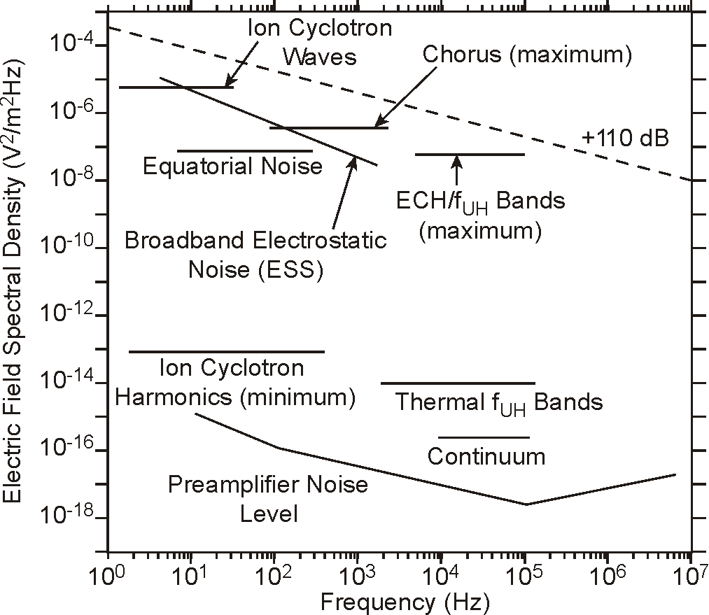
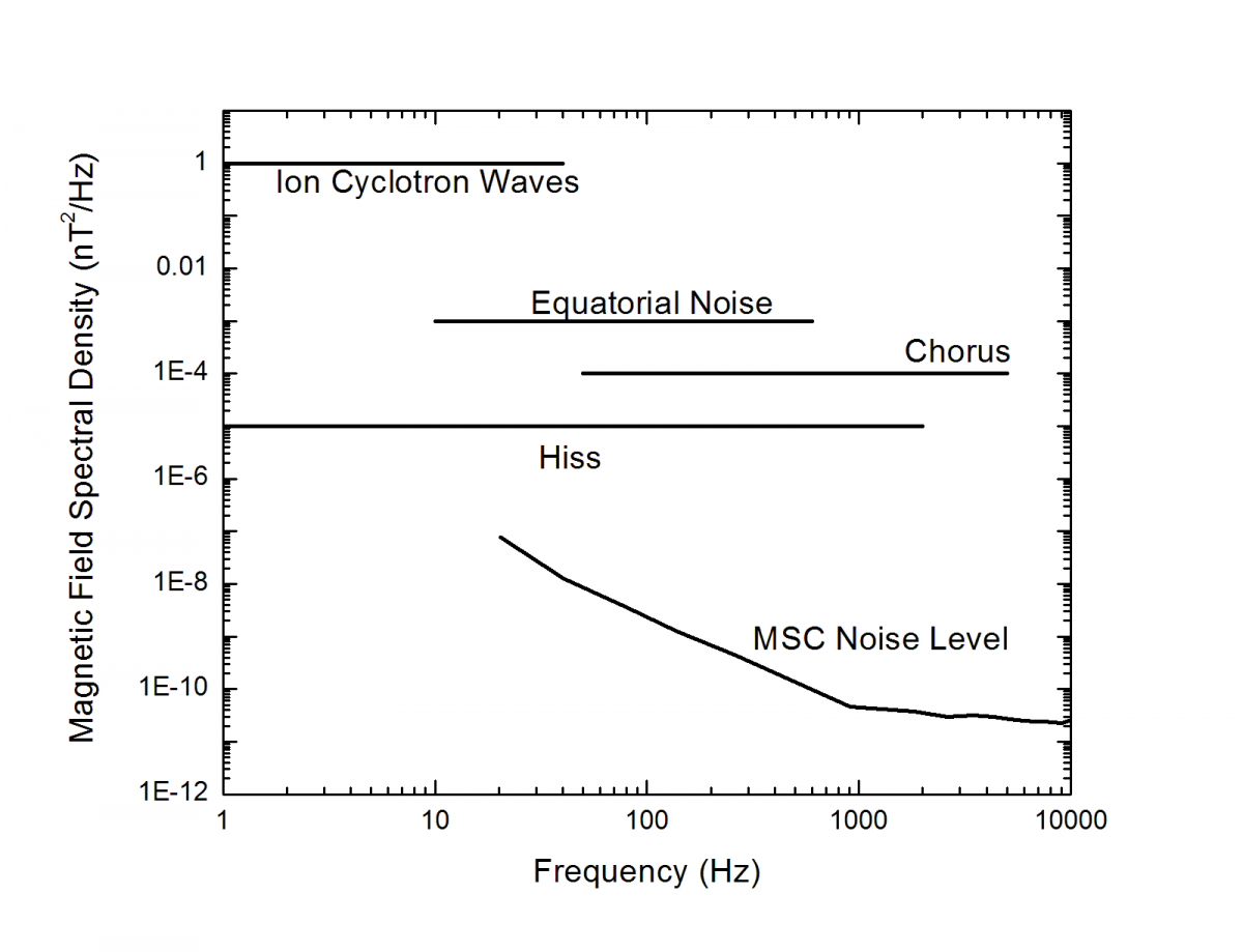
The instrument also provides a single electric field component of waves from 10 kHz to 400 kHz in order to measure the spectrum of electron cyclotron harmonic emissions and to measure the frequency of the upper hybrid resonance band, thereby providing an accurate determination of the electron density. Figure 15 and Figure 16 show the frequency range and amplitudes for the wave phenomena relevant to the Van Allen Probes objectives. The Waves instrument will have suitable dynamic range to cover all of these wave phenomena of relevance to radiation belt physics.
The electric field signals for the Waves instrument are provided to the EMFISIS instrumentation from the EFW experiment. These signals consist of differential voltages from opposing EFW spherical sensors. Two of these signals are derived from long wire booms in the spin-plane of the spacecraft. The third signal is provided by rigid booms mounted along the spacecraft axis
The Waves magnetic sensors consist of three identical search coil antennas mounted in a tri-axial configuration with each antenna oriented parallel to one of the spacecraft scientific (UVW coordinates) axes. Two are parallel to the two spin-plane EFW electric field double probes and the third is parallel to the spin axis double probe. The search coils are mounted on the boom opposite from the magnetometer boom to reduce any interference from the spacecraft. The spacecraft systems and other instruments have been designed and built with sound engineering practices that minimize electromagnetic interference.